
I love the original Ghostbusters movies. What’s not to love? Gadgets, the Rolls Royce of casts and crew, 80s humour and one of the most notable theme songs ever. My son who is five at the time of writing this, loves the Ghostbusters too! Now, I’ve tried hard not to push my son into anything and let him find his way. The only issue with that is the things I love, he wants to be involved in. He started watching the Ghostbusters cartoons from the 80s and for Christmas, Santa delivered a Ghostbusters outfit and a proton gun. In late April 2025, we watched the first movie. Of course, we had a big boy chat about knowing it’s a story and not being real! After all, he’s five and a 100-foot-tall marshmallow man might give him some reasons not to sleep or be hungry.
My boy goes out in his uniform, scans people to classify them, points his gun and then…ah wait. No trap.
This nightmare began with a 3d print
And so, a close friend figured he’d help out with the lack of trap. Help.
He grabbed the STL files for a trap and started printing. If you’ve never done anything like this before, having the files is just the start of the mission. A fully working model is something to behold and prints can require painting and careful assembly. Also, this is for a five-year-old, so it’s not going to a collector nerd that necessarily knows the difference between the original design and one that’s more fun.
Because this is an off-the-shelf print, I have limited choices of where to put things like batteries, electronics, connectors and such. Not impossible, just not easy either.
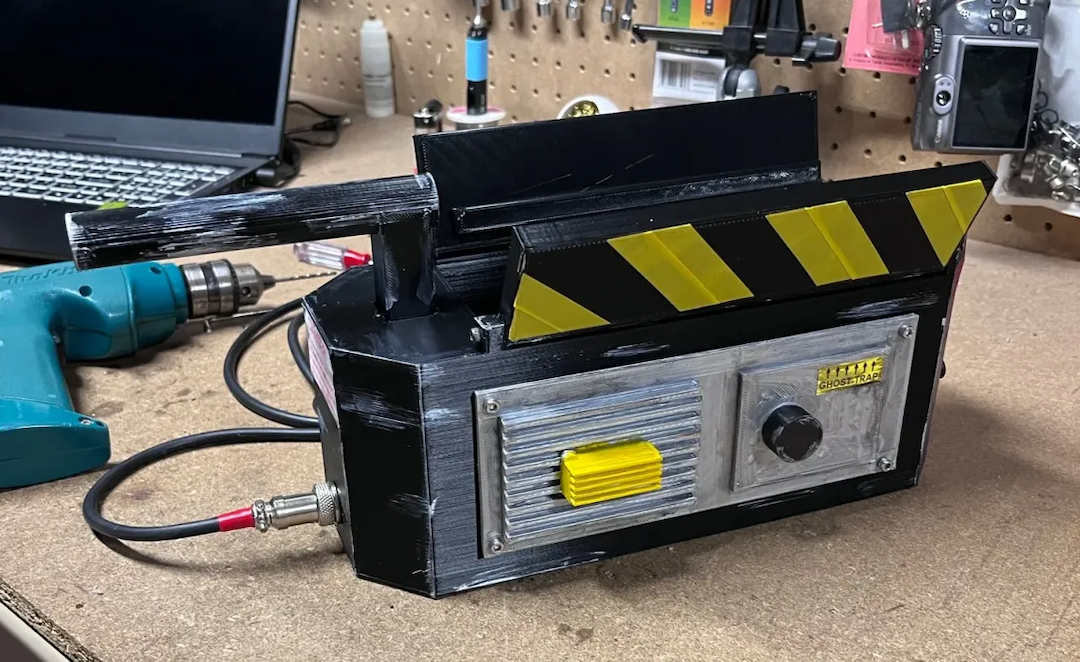
Below is an example of a finished trap from the STL files above, but not ours.
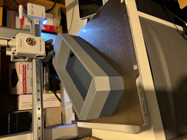
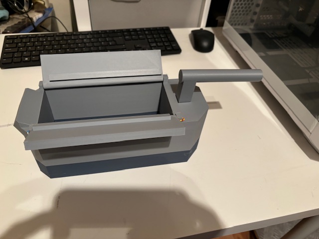
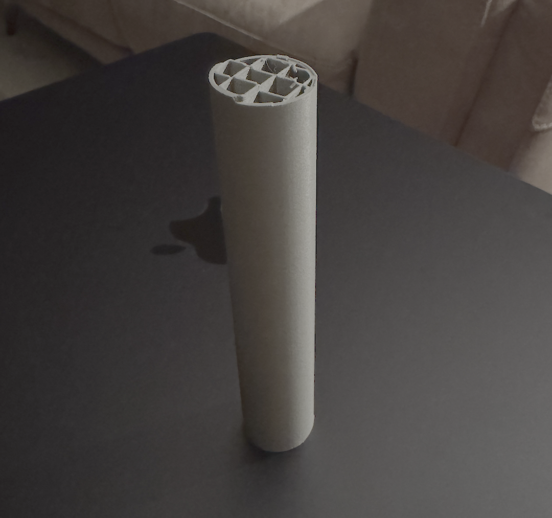
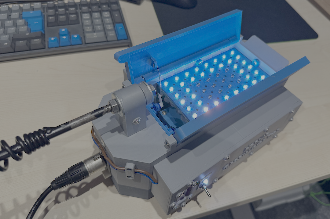
Next, a couple of photos from our trap, when it was printing and when all of the plastic components were completed!
What came next was figuring out a build plan and one that would make a five-year-old happy. These modern kids can’t be fobbed off easily and therefore, it had to be more than just something with opening and closing doors.
Feeling a sense of insurmountable requirements (and defeat), I started looking around at what I could buy. My days are incredibly busy, and my spare time is almost non-existent. I looked around on Etsy and my lord. £600 - £1000 for some reasonable functioning units and a ~£300 for something average.
Back to the drawing board. I made a plan.
- Whatever happens, it must be five year old proof
- Modern five-year-olds aren’t easily impressed so it must do more than just exist
- Motorised doors (finger safe)
- Smoke output (non-toxic and ideally water based)
- Flashing lights that would make a five-year-old crow with excitement
- Big battery because flat batteries are not compatible with five-year-olds
- No holes to stick fingers in and get burnt
- Accept it might not be aesthetically true to the movie
Nightmares you cannot wake up from
Alright. I buckled in and was in it for the long haul. First, I figured I would just assess the current situation and figure out how to open the doors via servo motors, so designed a servo housing, then re-designed the hatch doors and printed off a few variants of them, exploring various ways to mount the servos and played around with the positioning of the servo motors until the doors could be opened rapidly and easily without any friction. I also explored the linkage attachment points on the doors, moving their position, height and thickness etc until the doors opened properly and then self-limited their opening arc by the length of the servo link.
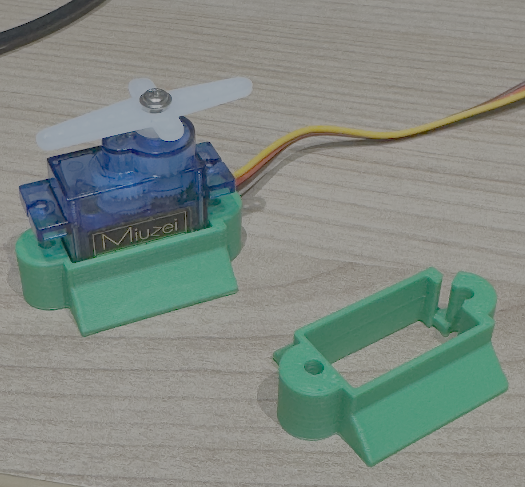
The wires are also in a bad position on these small micro servers, so needed a solution to not only house them and spread the torque but also manage the wires properly. I think it worked quite well!
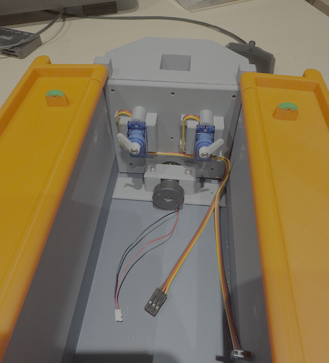
After a bit of trial and error, turns out the best material for servo linkages are good old fashioned paper clips. They bend and won’t cut little fingers off but are sturdy enough for heavy use. The thing in the middle at the bottom is a water atomiser and it creates vapour. I created a simple clamp to hold it in position. That bit worked out quite nicely. What you see above are prototype components and were in a long line up of disposed parts.
Confusing shop keepers
The next part of the plan was to implement the smoke. How the heck do I make this thing safely smoke? I researched water atomisers, vape burners, hemp burners, RC tank smoke generators and lots more. In fact, I now have an entire box of crap, dedicated to the art of kicking out smoke.
Turns out, burning oil with a heating coil is still the best way to get smoke out of a model. Water atomisers are great, but the primary issue is the vapour condenses pretty quickly if there is an obstruction in the path of the vapour. In a plastic model with electronics, water droplets are not recommended. Below is a vapour chamber I created to gather some atomised water and blow it out. Yeah, great in principle, but doesn’t work. This is why we test ideas out folks!
My next port of call was to wander around my local town and visit some of the fine merchants of vape products. I regularly got met with “New vape day sir?” style conversation and I like toying with folks when I’m in this mode, so asked vague questions and gave vague responses. “Want to try smoking it?” and I would respond “Oh no, I don’t smoke.”. The merchant would follow up with something like “So, you want to start vaping then?”. Eventually after a bit more toying, I would end with the diamond grade response: “It’s for my son. He’s five”. Fun aside, I now own two vapes, four vape tanks with rebuildable coils, a vape coil builder and tester, destroyed two complete vapes and accidentally breached a lithium battery with a knife. That battery is now in a bomb and fire-proof bag just in case it decides to release its magic smoke. I was kind of surprised at the level of engineering on these things. It’s astonishingly good. It annoys me further to know that people just buy these things as disposable units. Some of the vape tanks are works of engineering art, with solid aluminium interlocking and moving parts that feel superbly well made. The real win however was finding out about RC model Tanks that have smoke generators. It is possible to purchase a blower fan and heater for about £18, pre-made and you can also buy the pre-mixed oil for high smoke output from model shops. However, I’ve since found out a blend of baby oil and mineral oil works reasonably well and I’m working on a smoke generator for models/toys that can be built from readily available parts.
The sad part about the current trap is the water atomiser is installed, and it can be used sparingly, but with prolonged use, the expansion chamber fan bearings drown in water. I was under a sense of pressure with this, so the water atomiser remained. There is a secret plan to build a mark 2 😉
Flashy Fun
I’ve seen a fair few examples of these traps now on websites like Etsy. Most versions have some LED display, and I must admit, they were quite disappointing. I initially experimented with a low-tech hard-wired version of the display, with white LEDs, driven by a 4017 CMOS series decade counter. The idea being to have LED rings that would pulse inwards, like a vortex. The LED rings illuminated and distinguished slowly. It looked nice, but it was missing something, and I scrapped the idea.
Instead of the easy life, I opted to create a low resolution RGBW dot matrix display, complete with smoke holes. Spacing is everything and what you see below is perfectly designed for the space available in the trap.
I designed a screen with a mounting system for the enclosure and then started work on actually sourcing the LED components to make this screen. I found some addressable 5mm LEDs with the APA106 chipset and waited for them to be delivered. Then came the fun of assembly!
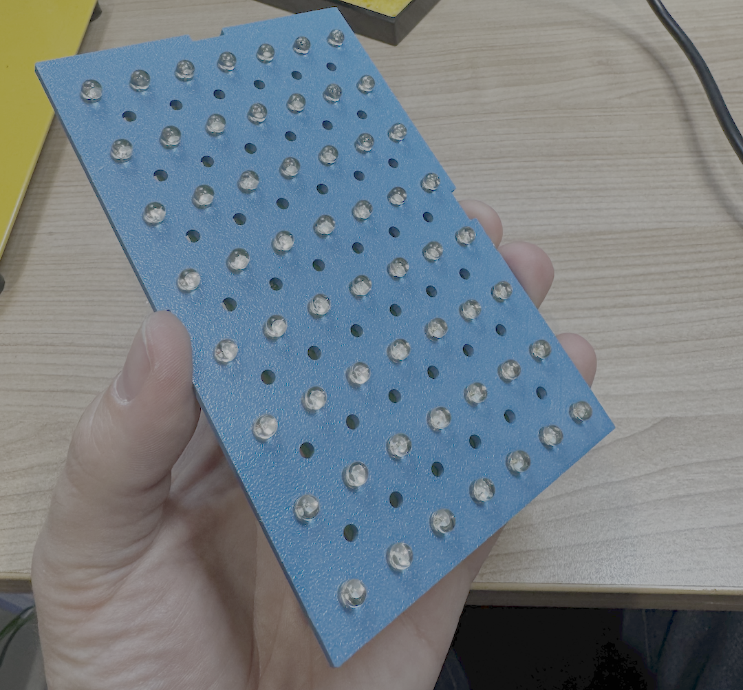
After a few days of waiting for China’s best to arrive, I mounted them and then cried into a beer whilst trying to solder 56 four pin LEDs. Not to be beaten, within an hour of giving up on the soldering effort I had designed a set of PCBs for the LEDs to sit on with headers to daisy chain together into a serpentine display. The PCBs arrived within 5 days, and it took about two hours to build a functioning display! Boom. Beer could go back to being tear free.

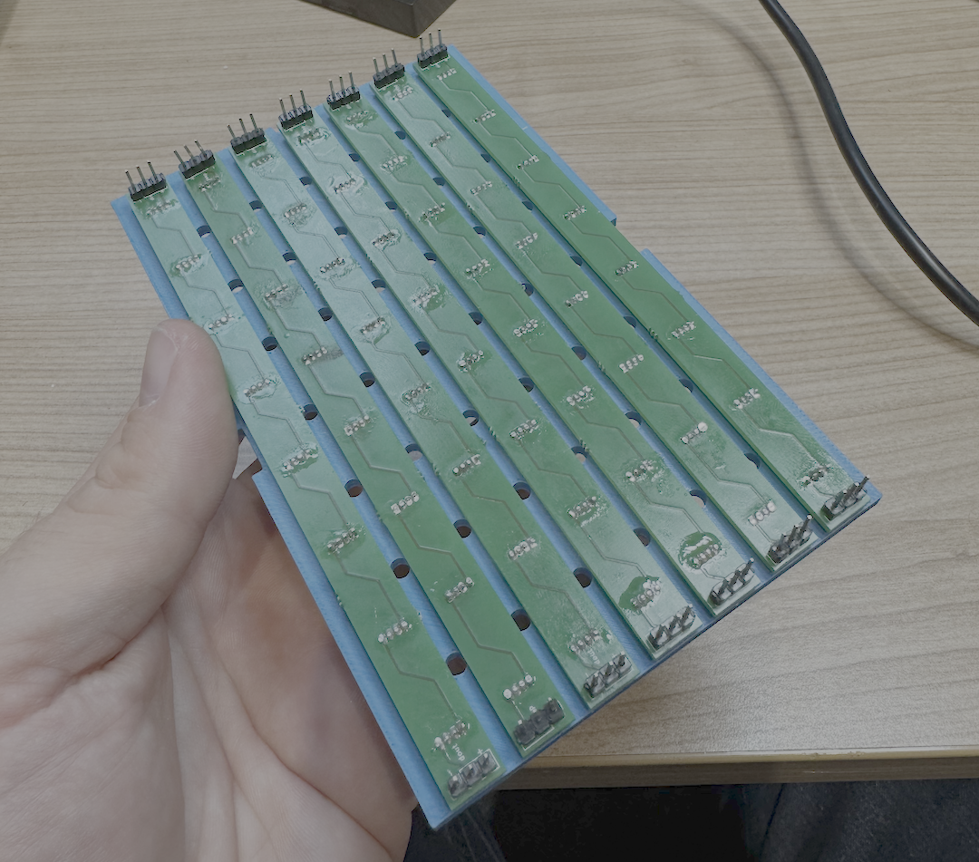
I knew programming a show, even on this super low-resolution screen was going to be a bit of a sod, so figured I’d address that issue post assembly. The most important part is the test program functioned just fine.
The Brains
I have a door mechanism, a smoke generator and now the internal light screen. Next up, was the control system. The trap process looks something like this:
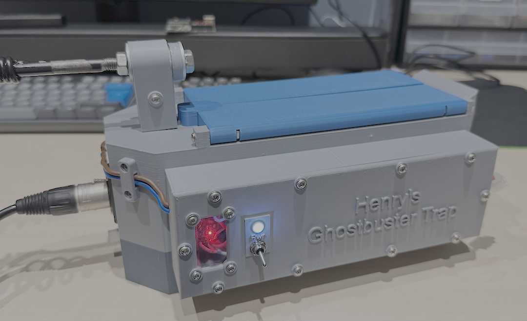
- Use mini switch to turn power on and light up LED power indicator
- Hit the pedal to start ‘trap process’
- Atomiser starts
- Light show begins
- Start fan
- Doors open
- Wait 10 seconds, add more smoke and drive lights
- Stop atomiser
- Wait two seconds
- Stop fan
- Close doors
- Stop light show
This was going to need a microcontroller of some description. The last time I really touched microcontrollers properly was almost twenty years ago. I went down a deep rabbit hole with this aspect, making the trips to vape shops look comical.
I started exploring the whole thing with 20-year-old microcontrollers, only to find my programming gear was so outdated, that it was a dead end. So, I ordered a new programmer which arrived within 24 hours and brought to life some old Microchip PIC 18F series devices. To my surprise, they worked quite well, but I had issues controlling some of the internal peripherals and figured age had not done them any favours. Straight out of the tube, the MCUs behaved differently, so threw them in the bin and ordered some new 16F13145 PICs that also appeared to have onboard CPLDs! Wicked. I could synthesise a nice steady clock and pulse system to drive the servos that don’t rely on interrupts!


My approach with this was to create a nice clock signal divider to generate a 0.5 mS clock train signal. The servos require a 1.5mS pulse to move anticlockwise and a 2 - 2.5mS pulse to move fully clockwise, all within a 20mS cycle. I figured with a steady pulse train, all I need to do is count the number of pulses to keep the output high for! Great. Apart from the numbers for the logical comparison didn’t work below or above certain numbers, resulting in synthesis failure. The logic gates simply couldn’t be routed. Specifically, I couldn’t use the number four, but I could use the number three and the number six. Go figure. Turns out synthesising this was out of the question because I was close to maximum usage of gates, despite how many times I tried to optimise it. Back to the drawing board. I had a rummage around in some boxes in the cupboard and found an Arduino Nano with an Atmega 328 onboard. That would have to do it.
The pedal that triggers the trap is attached to pin 2 on the Nano and has an external pull-up resistor. When the trap user hits the pedal, the input goes low, triggering the ISR on the Nano which then does a simple debounce. The pedal switching is very slow and noisy, so it took a bit of fiddling to get right, but got it figured out in the end.
A case of the shivers
The program for this is quite simple, especially with the libraries available to the Arduino range of devices. No more crafting servo libraries or LED libraries. It’s practically drag and drop.
The only issue experienced was the servos shivering on the trap doors. The LED light show uses an internal timer and that was affecting the servo timings. The easiest way around this problem is to attach the servos in code, move the servos to the desired positions, then detach them in code, giving enough time for them to move to the desired positions. This prevents the timing issues from appearing as shivers and solved the problem easily without spending time to optimise the ISR.
Building the circuit board
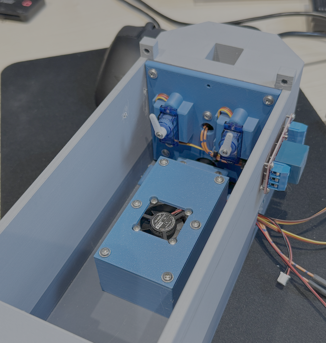
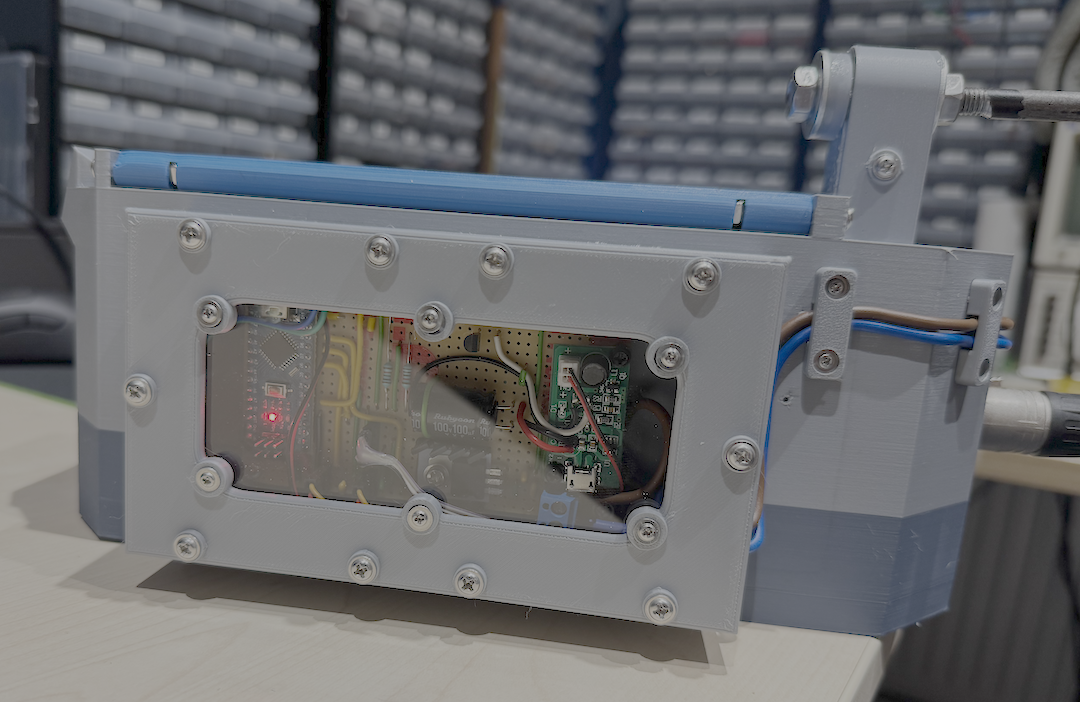
A bit more than an Arduino is required however for the onboard electronics. The Arduino is quite capable regarding digital pin source and sink capabilities but it’s not a superhero and additional components are required to drive the fan, atomiser and LEDs. It was time to dust off some old skills and build a stripboard circuit board for the trap. This by far was the longest task for the whole affair and took about six hours of messing about, soldering, drilling, making link wires and testing as I went.
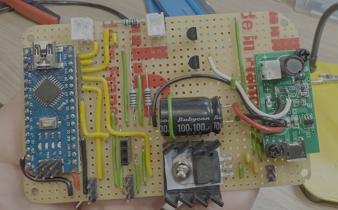
Also, the plan was to have this semi-visible on the side of the trap, so it had to look reasonably neat. Not too shabby for someone with rusty skills.
The 5V regulator is fairly beefy and I went down this route because it also looks cool. There are more power efficient regulators and power regulation strategies out there for sure, but this is old, tried and tested tech and adds a bit of steam punk feel with a heatsink. To control the fan and atomiser circuit, I used a pair of NMOS FET devices with current handling capabilities of about 0.3A, which is more than adequate for both tasks. I could have rebuilt the atomiser circuit instead of just mounting it, but time saved etc. The circuit for the atomiser is simple and nothing more than a 1.2khz resonance circuit to drive a transducer that atomises the water that is wicked through a foam rod. I have all the bits to re-create the circuit, but these boards are tiny, had screw holes and I was also curious if I could retrofit a control signal to it, which worked fine with 100mS pulses to control the onboard timer.
To make it easier to maintain, I added JST connector PCB sockets to the board for the fan and internal pedal connector, added female PCB strip header connectors for the servos and male PCB strip header connectors for the LED dot matrix display.
Finally, I made sure the power supply was robust and didn’t dip when peripherals turned on or off, or when the LED display was at full brightness with every LED lit. To help with that, a 5300mAh battery was installed and power flows through a dual NMOS high side driver, controlled by a small mechanical mini switch. For some external indication of power flowing properly through the high side driver, there is an LED power indicator, and its ground return also flows through the FET. Initially I wanted to do this with a relay, because the extra “thunk” sound of it turning on and off would just add to the magic, but dang, the current to keep the relay energised was just too high for my liking, so opted for the solid-state approach.
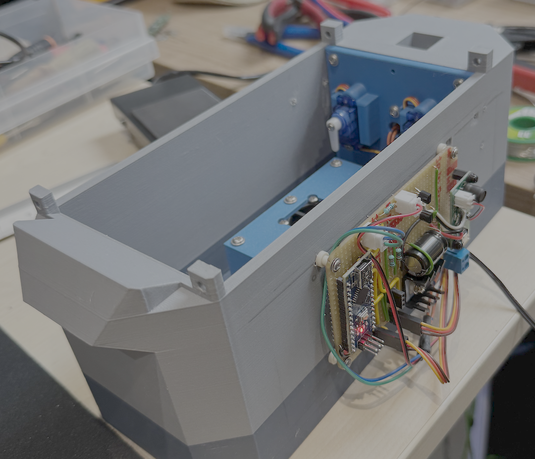
Next, I designed a battery pack enclosure, that would be screwed and glued to the side of the trap body, requiring some creative wiring.

The other task remaining was to also create a housing for the circuit board and cut some perspex, so it’s possible to see inside, without little fingers pulling out wires or getting themselves burnt. I’m reasonably skilled with CAD and had those drawn up and being printed within 15 minutes.
Stop! Frame animation…
One of the final tasks left to complete was the light show itself, requiring a choreographed scene. No biggie! I’ll just write the show in code… …more tears into beer.
To make this less painful, I instead wrote a React based web app animator for the LED screen, which generates the C/C++ code for the Arduino. Using my web animator, you then directly program the stop frame animation sequences on to the screen by clicking LEDs and setting the colour and intensity. It has a preview function and makes a tedious task simple. It was a bit of a smile maker, especially with the animated preview. You can see the animator web app in the video at the end of this blog.
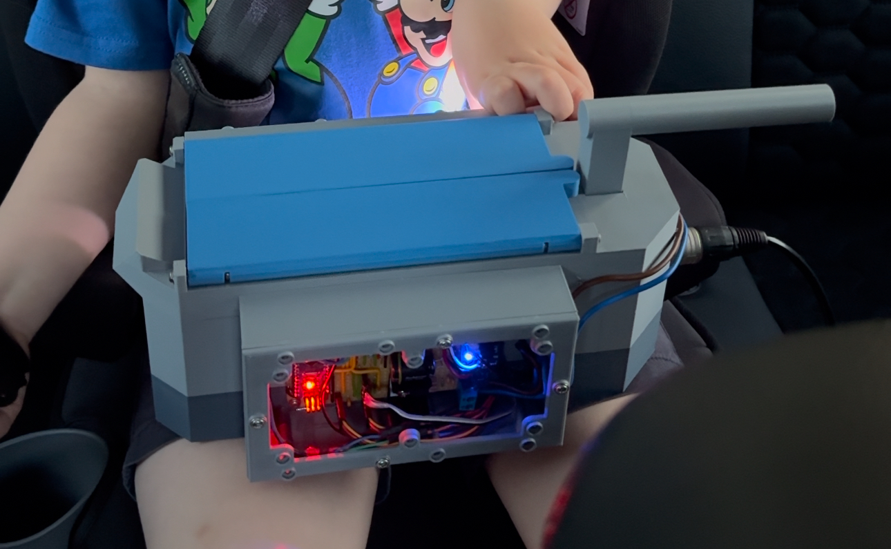
Safety screens and being careful
Next up, we took it out on an afternoon trip, in an 85% finished state. My son “helped” me finish it before heading out and it naturally needed to come with us. So be it, but it was naked. The circuit board was touchable and there wasn’t any protective cover on the power transmission side. My boy was under strict instruction not to poke fingers in certain areas, not to get it wet or drop it.
It survived the trip and later that night, I finished the trap off properly by cutting some small perspex covers for the electronics areas, glued and screwed those on, designed and printed up some cable cleats and then a few seconds after success and feeling quite smug, knocked the trap off my desk and on to the floor.
The handle snapped clean off.
Handling the incident
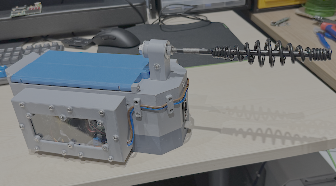
In my wisdom, I had also glued in the handle and screwed it. The remaining part of the handle that was still attached wasn’t budging. My son was now asleep, dreaming of waking up to play with the trap and I had just lectured the kid about not breaking it. Things were looking bleak, and egg was aligned with face. I had also run out of beer, so nothing to cry into either. I went into the garage to have a letch about and figure out what was possible. I didn’t have any mild steel or aluminium raw stock small enough to make a handle. I can weld and braze to fabricate parts, so no issue, but no material, so that’s not happening. I even considered casting one from aluminium, but it was already late at night, and I couldn’t see me getting that done within the time remaining before my son woke up. I started playing with a stick welding hammer whilst thinking about what handle I could make. It needed to be retro looking (like a welding hammer), be long enough to help with carrying the weight of the trap (like the welding hammer) and have an M8 thread (not like the welding hammer). What if there was a handle I could cut off something (like the welding hammer), that had an 8-8.2mm rod (like the welding hammer…wait a minute) for me to thread! Within sixty seconds, the hammer head was sawn clean off and I threaded 60mm worth of M8 thread on to the spanky new trap handle. I think the new handle suits it better anyway.
The next challenge was to strengthen up the plastic stub now sticking out of the trap. After a quick measure up, I created a strengthening jacket for the stub which had alignment holes for the new handle, along with a plastic washer to hide the damage from where the old handle sheared and also made some stainless steel M8 penny washers to spread the weight of using the new handle across the plastic stub. Behold the new(ish) and improved(ish) handle is below.

Note, the white tube below the XLR connector is in fact the foam atomiser rod. To get ‘smoke’ out of the atomiser, the foam rod needs to be ran under a cold water tap, and plugged into to the hole in the rear of the trap, snuggly pushed up against the aomiser. Second point, it annoys me something chronic, that the XLR connector isn’t dead centre. Long story short, the drill snagged when boring the hole. I managed to recover it, but it shredded the rear of the enclosure, despite me trying to be careful as possible.
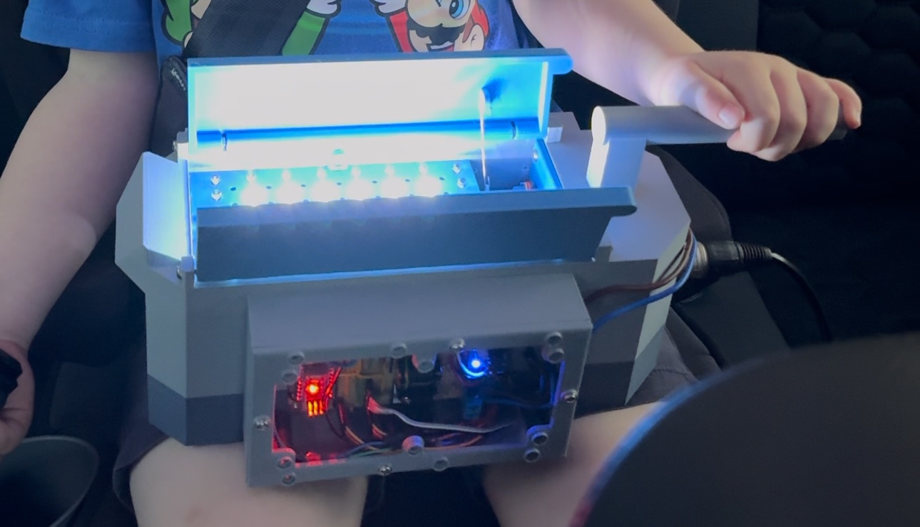
Happy kiddo
In the video below, you can see a short snippet of it running at night to get an idea of the brightness of the LEDs! It really is quite blinding and the colour distribution on the LEDs is beautiful. White is generated from all the colours being on full brightness and the side effects of that are just great.
Next I’ll improve the light show now the pressure is off, adding more frames with a bit of colour and brightness variance, then secretly I’ll start work on mark 2, which will be closer to the movie design, in a black body, with the hazard tape and retro electronics kit. I’ll redesign the whole unit and find ways to hide the electronics and battery, along with integrating an oil-based smoke generator.
For now, it’s a functioning toy and my son is a little smitten.
Outcome
- One happy boy!
- Four months of barely-spare time consumed
- Approx 16-20x pints of beer drank
- At least a family size box of snacks eaten
- Generated ~15ml of tears
- Created a box of experimental parts
- One damaged lipo battery to properly dispose of
- I have a fine collection of vape and herb burning kit to be proud of (I don’t vape or smoke)
- Creation of a very stubby welding hammer (I’ll need this one day and will have forgotten)
- Spent £130ish on parts, which includes filament to do the printing
- A strong suggestion of he now would like:
- A backpack
- A P.K.E. meter (Aurascope)
I might do both the backpack and P.K.E. meter, because despite the tears and many swear words recited, I quite enjoy tinkering. Making toys for my son is super rewarding and it’s a gift for me to be able to it.
If you are interested in replicating this, then you’ll need the following:
- 250mm x 250mm x 150mm 3d printer (l x w x h)
- Soldering iron and average soldering skill
- JST crimps
- 56x APA106 LEDs (5mm, four pin)
- 1x White 5mm LED
- 1x NMOS logic drivable high side driver for the battery
- 1x 5300mAH battery
- Mini switch
- Foot pedal switch
- XLR female wire plug
- XLR panel male connector
- Various wire
- Through hole components like 0.3A NMOS, resistors, and header connectors
- Strip board and strip board drill bit
- 2x 180* mini servos
- 2x standard grey bare metal paperclips
- 1x 35mm 5v fan
- Small sheet of clear 2mm perspex
- Sharp Stanley knife
- Small hand drill and selection of drill bits (0.3mm - 3mm)
- 1x Arduino Nano or Atmega 328 through-hole MCU
I’m happy to share my STL files and code if you get stuck.
Watch this space for a much truer version of the trap from the movies!