
This article is focused on a basic area of networking. Apologies to any readers who want meatier stuff! Regularly I get approached with questions and conversational topics around VRFs. These questions come from a myriad of people, both young and old(er), experienced and the not so experienced. Questions like:
• What are they?
• How do they work?
• How do I connect VRFs together?
• Do I need them in my network?
Before I jump in to the body of this post, I also wish to highlight that I will be terming anything that can route IP packets a “routing system”.
Let’s start with the actual meaning. VRF’s are “Virtual Routing and Forwarding” instances, but as that’s a mouthful, they’re pronounced “vee arr effs” or “verfs”. VRFs allow multiple isolated routing tables to exist on a routing system. If multiple VRFs exist on an Ethernet trunk, then VRF’s also facilitate path isolation. VRFs provide private RIBs and FIBs for each customer. Nothing more!
Vendors muddy the waters as they always do and instead of just being happy with terming it a VRF, Cisco for instance calls them VRF-Lite for scenario’s where VRFs are used without an MPLS backbone. With later code, Cisco has dubbed the next rendition of VRF-Lite, EVN or Easy Virtual Networking. They’re still VRFs right?!
How do we connect VRFs together? Well, as VRFs are no more than isolated routing and forwarding tables, the answer is derived from the requirement of the VRF in the first place. There isn’t really a single answer to this question, only, “it depends”. Below is a non-exhaustive list of VRF interconnection methods.
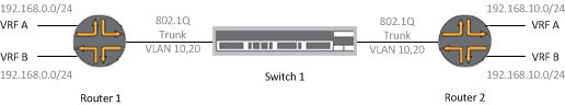
L3 Tagged Subinterface/Logical Interfaces This method could allow two routing systems to provide customer multi-tenancy. Side A routing system has a tagged sub/logical interface configured for a specific VRF on the client side (far left or far right). The sub/logical interface facing the neighbouring device (switch or router) has an address which belongs to a transit LAN or point-to-point L3 link. The B side transit LAN would have a L3 address in the address range of side A’s transit LAN. Each customer would have a specific VLAN tag which would allow their Ethernet frames containing the customer specific IP packet to get tagged and traverse the link. This also means each customer could use exactly the same address space. In terms of order of operation, the L2 VLAN tag would be dealt with first, then the route lookup gets performed referencing the VRF of the interface that the packet arrives on. This system provides IP separation which is dependent on L2 segregation.
EVN was touched on very lightly above. Cisco EVN really is just a configuration shift and does not offer any additional technological advancement. I guess this development could derive from misunderstanding VRFs in the first place?
Below illustrates this method of connectivity with configuration for Cisco IOS and Junipers Junos. The ingress and egress to each VRF hangs to the far left and far right of the diagram. Each VRF has a subinterface on the router for the point-to-point link, which allows each separate routing table to communicate in isolation. VRF_A has the VLAN 10 tag and VRF_B has the VLAN 20 tag. Both of these VLANs traverse the 802.1Q Ethernet trunk via the switch. The far left and far right interfaces can be tagged or untagged depending on the deployment requirement. As the devices in this instance are routers, the far left/right CE (customer facing) interfaces can be tagged with an arbitrary number. Each interface acts independently. Address space although overlapping in this example is isolated.
Cisco IOS Configuration (Side A)
vrf definition VRF_A
description Customer A VRF
!
address-family ipv4
exit-address-family
!
address-family ipv6
exit-address-family
!
!
vrf definition VRF_B
description Customer B VRF
!
address-family ipv4
exit-address-family
!
address-family ipv6
exit-address-family
!
!
int gig 0/0
no shut
!
!
int gig 0/0.10
description "Customer A VRF"
encapsulation dot1Q 10
vrf forwarding VRF_A
ip address 10.10.10.1 255.255.255.252
no shut
!
!
int gig 0/0.20
description "Customer B VRF"
encapsulation dot1Q 20
vrf forwarding VRF_B
ip address 10.10.10.1 255.255.255.252
no shut
!
!    Customer Links Below. Note that
!    VLAN tags can be different or non-existant!
!
int gig 0/1
description "Customer A CE Link"
encapsulation dot1Q 10
vrf forwarding VRF_A
ip address 192.168.0.1 255.255.255.0
no shut
!
!
!
int gig 0/2
description "PE Multi-VRF Trunk Link"
no shut
!
int gig 0/2.50
description "Customer B CE Link"
encapsulation dot1Q 20
vrf forwarding VRF_B
ip address 192.168.0.1 255.255.255.0
no shut
Operational Commands
show ip route vrf VRF_A
show ip route vrf VRF_B
ping vrf VRF_A 10.10.10.x
ping vrf VRF_B 10.10.10.x
Juniper Junos Configuration (Side A)
routing-instances {
/*Worth explaining that the route-distinguisher is a required statement. Without BGP VPNv4 sessions, they don't do anything. vrf-target added for completion. 65500 = private BGP ASN.*/

VRF_A {
instance-type vrf;
interface ge-0/0/0.10;
interface ge-0/0/1.0;
route-distinguisher 65500:1;
vrf-target target:65500:1;
}
VRF_B {
instance-type vrf;
interface ge-0/0/0.20;
interface ge-0/0/2.20;
route-distinguisher 65500:10;
vrf-target target:65500:10;
}
}

edit interface ge-0/0/0>

unit 10 {
description Customer A VRF;
vlan-id 10;
family inet {
address 10.10.10.1/30;
}
}

unit 20 {
description Customer B VRF;
vlan-id 20;
family inet {
address 10.10.10.1/30;
}
}

edit interface ge-0/0/1>

unit 0 {
description Customer A VRF;
family inet {
address 192.168.0.1/24;
}
}

edit interface ge-0/0/2>

unit 20 {
description Customer B VRF;
vlan-id 50;
family inet {
address 192.168.0.0/24;
}
}
Operational Commands
run show route table VRF_A.inet.0
ping routing-instance VRF_A 10.10.10.1
IP Tunnelling Across a Shared IP Network
IP tunnelling and GRE options allow a scenario where an existing L3 link already exists, but a new department, customer or solution requiring IP separation is required. This could even be a company merger or acquisition. The source packet is sent to a PE node VRF, encapsulated with the new header (GRE) and then routed across the underlying IP network, to arrive at its destination. The packet is then de-encapsulated and routed out of the egress interface via the VRF to its final destination. This is more of an overlay solution than real world scenario, but this type of separation is common when dealing with NAC scenarios, multi-tenancy, WiFi and low-cost ISP networks. This method also introduces an MTU reduction prior to fragmentation as the additional headers take up valuable head space. Overlays are becoming popular with the ever-increasing take up of SDN so watch out for more of this.
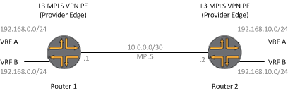
Multi-Protocol Label Switching [MPLS]
This one is a bit more complex to describe (whole bookshelves have been devoted to this subject – this is a light touch). MPLS is the process of tagging a frame of with a number. That frame then gets moved on at Layer 2.5. (not quite L2, not quite L3, a shim layer if you will). This number gets imposed on to a frame, inspected, swapped and popped at nodes in a network path. This number is the “Label”. MPLS requires that the underlying network supports MPLS. If it doesn’t, IP tunnelling or MPLSoGRE might be your saviour. With the advent of SDN, MPLSoIP is becoming a popular transit method. MPLS requires a method to swap labels with peer systems. Label Distribution Protocol being one of them, inspects the routing table, assigns a label to an IGP prefix (Cisco) or a node loopback address (Juniper’s Junos) and sends it on to a peer. BGP has extensions for sending labels and RSVP can provide information to peer systems on paths and endpoints. The diagram below illustrates a typical L3 MPLS VPN. The phrase “a picture can say a thousand words” really shines here!
Other Methods
VRF Route-leaking, Junos logical tunnels and Cisco VASI are all worth a look in.
Real World Uses
VRFs are super useful tools. Typical use cases include isolating network device management traffic, facilitating customer separation and providing central service VPNs which allow a service provider’s shared management platform to have visibility of customer devices on associated VRFs.
Note: As VRFs are device constructs only and not a protocol, no additional headers are added to any packets that traverse them. This is a massively misunderstood fact around VRFs.