
Traditional and modern Enterprises often suffer from inflexible service providers either charging over the odds, taking forever to make changes, or providing overly complex and unreliable services. SDN is beginning to threaten the way things are done in the data centre and enterprise, moving all the complexity up to a different level. The dawn of the Overlay and Underlay networks is here. Simple flat L2 and hardware switched L3 networks are pretty much the only requirement for SDN based networks, with a few exceptions, the edge being one of them. In terms of the traditional campus design methodology, WAN and internet connectivity modules will *always be required. Service Providers will always try and monetize and generate additional revenues from old tired featureless equipment. The problem for the lazy providers is the rest of the world has got smarter. What was once bleeding edge tech, is now mature, predictable and part of network consultants and engineers day to day tool set.
Recently a requirement was raised to stretch a L2 VLAN between two customer sites that are connected via a typical L3 MPLS VPN service. Just to clarify here, this results in a simple L3 network and the customer does not interact with MPLS itself (sorry, I have seen CV’s from people claiming to have MPLS experience. This is not MPLS exposure. Just L3!). The requirement more specifically was to stretch L2 between two L3 connected sites to provide seamless migration of virtual machines. In a mature IT department, many physical servers underwent virtual consolidation in round one of VMware’s onslaught a long time ago (in IT years). Under rebuild scenarios, the servers would get built and each software service would get scrutinized. Old unused services would get removed and used services would get upgraded or patched. When P2V occurs, there isn’t (without a good reason) a need to rip apart known working machines, so a state is reached where departments do not have deep knowledge as to what is running where on what. Stretching a VLAN and migrating the virtual machines between two different data centres allows for some shy eyes during a stressful migration processes. So, how do you do this when presented with a L3 network? Straight away, a Cisco house running traditional IOS based devices would push for L2TPv3, which works. Create a L2 tunnel. Job done. If you have ever tried implementing L2TPv3 tunnels, you will know either you have to introduce extra equipment (depending on current model of router or performance requirements etc.), or cable up additional ports in order to bridge from a LAN/VLAN to the port which is configured as an ‘xconnect’, in some instances on the same line card or switch. Nexus7K devices provide OTV which will provide the DCI in this instance, but OTV comes with its own topological requirements (and hefty price tag).
Here are the requirements with more detail:
a) L2 Stretch between two DC’s over pure L3 network
b) No changes to provider network to avoid cost
c) Cannot install an additional WAN circuit
d) Try and avoid installing additional kit
e) No interruption to current traffic flows
f) Avoid kludges1
g) Prepared to sacrifice some MTU headroom
I add at this point, the current network is running Juniper SRX210’s as the CPE device which replaced previous J series devices. These are running in packet forwarding mode with future plans to make them flow based post migration.
Can this be done with the SRX210’s alone? Absolutely. Does it perform? You bet. Does it break sweat? Not really. Do you need extra cabling? Nope.
Juniper are known for superiority in the Service Provider space and all things MPLS. If you’ve read any other articles on this site, you will know I love Junos. Its flexibility astounds me and their vision of the future has me excited. In this instance, Junos provides an elegant way to meet the requirements and also provide local internet breakout at each site with first hop resiliency for ingress and egress of the stretched LAN/VLAN. With some scripting and RPM usage, you could also add features like auto failover just in case the internet uplink died or became unavailable. Cool stuff.
The solution is based on VPLSoGRE with VRRP used for the FHRP. This would also be possible with AToM (Any Traffic over MPLS) using a L2CKT, Ethernet or VLAN circuit cross connect (CCC), but I went with VPLS as I like to build scalable topologies. With the Juniper MX, this would be a straight forward design to implement. You would create an irb group (integrated routing and bridging) and add the interfaces in to the VPLS instance. The SRX branch products do not support irb when used in this way (as I found out when trying to configure it!). So how do you do it? The trick I found was to use logical tunnel interfaces (lt-0/0/0) in addition to running VRRP between each peer logical-tunnel unit that sits in the global routing table on each device. Who’d of thunk it?
Before I dive in to the configuration, we need to take a brief look at the MTU side effect. With MPLSoGRE, if we assume 1500byte starting IP MTU for the WAN circuit, we can deduct another 24 bytes for GRE (20 bytes for the new IP header, plus 4 bytes for the GRE header without any other GRE mechanisms) and 8 bytes for 2x MPLS labels (more on that shortly). So we’ve reduced the MTU to 1500 – (24+8) = 1464 bytes before fragmentation is required. Whilst I’ve seen worse MTU on consumer broadband, in an enterprise or data centre environment, it’s worth investigating just how big the packets are moving between those VM’s and hosts in the same VLAN as fragmentation can and will have an effect on CPU load.
Not that it’s hard to picture, below is an image which represents the test environment. You might have to click on the image in order to view the detail. One of the problems from having a narrow blog!
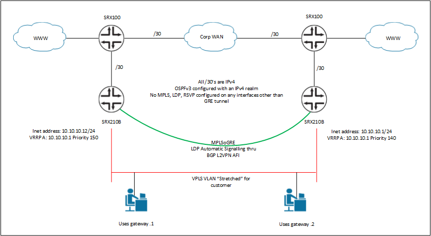
As a summary, each device participates in OSPFv3 which also has the IPv6 realm knob configured so that we can use just one IGP for both IPv4 and IPv6. For the sake of simplicity, all direct and local routes are redistributed into the OSPFv3 process, which means end-to-end connectivity is in place between each device. This means each device can ping every other device via its loopback and point-to-point interface. Between each SRX210, a GRE tunnel is nailed up, BGP is configured to work with the ‘l2vpn’ family, which provides signalling for VPLS end points and LDP finishes the story off by providing the label swapping mechanism. You can of course configure this topology without BGP, but adding hosts can become cumbersome. BGP configured in this way advertises the location of VPLS endpoints for LDP to automatically target. In larger networks, it is wise to use a pair of BGP route-reflectors, else scaling again becomes an issue as everything is considered point-to-point without the RR’s. When trying to build anything like this, from a high level view, what you’re actually doing is fully meshing the control-plane and the data-plane with BGP and LDP respectively.
There are various show commands that can be submitted to each device to prove the correct operation of each protocol. SRX1 is the bottom left hand side SRX210, SRX2 is the SRX210 on the bottom right hand side device. SRX3 and SRX4 are the top left and top right SRX devices respectively.
root@SRX1# run show ldp session detail
Address: 2.2.2.2, State: Operational, Connection: Open, Hold time: 24
Session ID: 1.1.1.1:0--2.2.2.2:0
Next keepalive in 4 seconds
Passive, Maximum PDU: 4096, Hold time: 30, Neighbor count: 1
Neighbor types: discovered
Keepalive interval: 10, Connect retry interval: 1
Local address: 1.1.1.1, Remote address: 2.2.2.2
Up for 09:20:09
Capabilities advertised: none
Capabilities received: none
Protection: disabled
Local - Restart: disabled, Helper mode: enabled
Remote - Restart: disabled, Helper mode: enabled
Local maximum neighbor reconnect time: 120000 msec
Local maximum neighbor recovery time: 240000 msec
Nonstop routing state: Not in sync
Next-hop addresses received:
gr-0/0/0.0
172.16.0.2


root@SRX2# run show ldp session detail
Address: 1.1.1.1, State: Operational, Connection: Open, Hold time: 29
Session ID: 2.2.2.2:0--1.1.1.1:0
Next keepalive in 9 seconds
Active, Maximum PDU: 4096, Hold time: 30, Neighbor count: 1
Neighbor types: discovered
Keepalive interval: 10, Connect retry interval: 1
Local address: 2.2.2.2, Remote address: 1.1.1.1
Up for 09:20:23
Capabilities advertised: none
Capabilities received: none
Protection: disabled
Local - Restart: disabled, Helper mode: enabled
Remote - Restart: disabled, Helper mode: enabled
Local maximum neighbor reconnect time: 120000 msec
Local maximum neighbor recovery time: 240000 msec
Nonstop routing state: Not in sync
Next-hop addresses received:
gr-0/0/0.0
172.16.0.1


root@SRX1# run show ldp database
Input label database, 1.1.1.1:0--2.2.2.2:0
Label Prefix
299776 1.1.1.1/32
3 2.2.2.2/32

Output label database, 1.1.1.1:0--2.2.2.2:0
Label Prefix
3 1.1.1.1/32
299776 2.2.2.2/32


root@SRX2# run show ldp database
Input label database, 2.2.2.2:0--1.1.1.1:0
Label Prefix
3 1.1.1.1/32
299776 2.2.2.2/32

Output label database, 2.2.2.2:0--1.1.1.1:0
Label Prefix
299776 1.1.1.1/32
3 2.2.2.2/32


root@SRX1# run show vpls connection
Instance: VPLS
  BGP-VPLS State
  Local site: R1 (1)
    connection-site           Type  St     Time last up          # Up trans
    2                         rmt   Up     Jun 18 16:29:50 2013           1
      Remote PE: 2.2.2.2, Negotiated control-word: No
      Incoming label: 262146, Outgoing label: 262145
      Local interface: lsi.1048576, Status: Up, Encapsulation: VPLS
        Description: Intf - vpls VPLS local site 1 remote site 2
  LDP-VPLS State
  VPLS-id: 600


root@SRX2# run show vpls connection
Instance: VPLS
  BGP-VPLS State
  Local site: R2 (2)
    connection-site           Type  St     Time last up          # Up trans
    1                         rmt   Up     Jun 18 16:25:54 2013           1
      Remote PE: 1.1.1.1, Negotiated control-word: No
      Incoming label: 262145, Outgoing label: 262146
      Local interface: lsi.1048576, Status: Up, Encapsulation: VPLS
        Description: Intf - vpls VPLS local site 2 remote site 1
  LDP-VPLS State
  VPLS-id: 600


root@SRX1# run show bgp neighbor
Peer: 2.2.2.2+63588 AS 56518   Local: 1.1.1.1+179 AS 56518
  Type: Internal    State: Established    Flags:
  Last State: OpenConfirm   Last Event: RecvKeepAlive
  Last Error: None
  Options:
  Address families configured:  l2vpn-signaling
  Local Address: 1.1.1.1 Holdtime: 90 Preference: 170
  Number of flaps: 0
  Peer ID: 2.2.2.2         Local ID: 1.1.1.1           Active Holdtime: 90
  Keepalive Interval: 30         Peer index: 0
  BFD: disabled, down
  NLRI for restart configured on peer: l2vpn
  NLRI advertised by peer: l2vpn
  NLRI for this session: l2vpn
  Peer supports Refresh capability (2)
  Stale routes from peer are kept for: 300
  Peer does not support Restarter functionality
  NLRI that restart is negotiated for: l2vpn
  NLRI of received end-of-rib markers: l2vpn
  NLRI of all end-of-rib markers sent: l2vpn
  Peer supports 4 byte AS extension (peer-as 56518)
  Peer does not support Addpath
  Table bgp.l2vpn.0
    RIB State: BGP restart is complete
    RIB State: VPN restart is complete
    Send state: not advertising
    Active prefixes:              1
    Received prefixes:            1
    Accepted prefixes:            1
    Suppressed due to damping:    0
  Table VPLS.l2vpn.0 Bit: 20000
    RIB State: BGP restart is complete
    RIB State: VPN restart is complete
    Send state: in sync
    Active prefixes:              1
    Received prefixes:            1
    Accepted prefixes:            1
    Suppressed due to damping:    0
    Advertised prefixes:          1
  Last traffic (seconds): Received 24   Sent 10   Checked 43
  Input messages:  Total 56     Updates 2       Refreshes 0     Octets 1184
  Output messages: Total 57     Updates 1       Refreshes 0     Octets 1222
  Output Queue[0]: 0
  Output Queue[1]: 0


root@SRX1# run show route table VPLS.l2vpn.0
VPLS.l2vpn.0: 2 destinations, 2 routes (2 active, 0 holddown, 0 hidden)
+ = Active Route, - = Last Active, * = Both

1.1.1.1:600:1:1/96
                   *[L2VPN/170/-101] 00:37:52, metric2 1
                      Indirect
1.1.1.1:600:2:1/96
                   *[BGP/170] 00:36:17, localpref 100, from 2.2.2.2
                      AS path: I
                    > to 172.16.0.2 via gr-0/0/0.0


root@SRX2# run show bgp neighbor
Peer: 1.1.1.1+179 AS 56518     Local: 2.2.2.2+63588 AS 56518
  Type: Internal    State: Established    Flags:
  Last State: OpenConfirm   Last Event: RecvKeepAlive
  Last Error: None
  Options:
  Address families configured:  l2vpn-signaling
  Local Address: 2.2.2.2 Holdtime: 90 Preference: 170
  Number of flaps: 0
  Peer ID: 1.1.1.1         Local ID: 2.2.2.2           Active Holdtime: 90
  Keepalive Interval: 30         Peer index: 0
  BFD: disabled, down
  NLRI for restart configured on peer: l2vpn
  NLRI advertised by peer: l2vpn
  NLRI for this session: l2vpn
  Peer supports Refresh capability (2)
  Stale routes from peer are kept for: 300
  Peer does not support Restarter functionality
  NLRI that restart is negotiated for: l2vpn
  NLRI of received end-of-rib markers: l2vpn
  NLRI of all end-of-rib markers sent: l2vpn
  Peer supports 4 byte AS extension (peer-as 56518)
  Peer does not support Addpath
  Table bgp.l2vpn.0
    RIB State: BGP restart is complete
    RIB State: VPN restart is complete
    Send state: not advertising
    Active prefixes:              1
    Received prefixes:            1
    Accepted prefixes:            1
    Suppressed due to damping:    0
  Table VPLS.l2vpn.0 Bit: 20000
    RIB State: BGP restart is complete
    RIB State: VPN restart is complete
    Send state: in sync
    Active prefixes:              1
    Received prefixes:            1
    Accepted prefixes:            1
    Suppressed due to damping:    0
    Advertised prefixes:          1
  Last traffic (seconds): Received 27   Sent 12   Checked 76
  Input messages:  Total 56     Updates 2       Refreshes 0     Octets 1144
  Output messages: Total 57     Updates 1       Refreshes 0     Octets 1222
  Output Queue[0]: 0
  Output Queue[1]: 0


root@SRX2# run show route table VPLS.l2vpn.0
VPLS.l2vpn.0: 2 destinations, 2 routes (2 active, 0 holddown, 0 hidden)
+ = Active Route, - = Last Active, * = Both

1.1.1.1:600:1:1/96
                   *[BGP/170] 00:36:23, localpref 100, from 1.1.1.1
                      AS path: I
                    > to 172.16.0.1 via gr-0/0/0.0
1.1.1.1:600:2:1/96
                   *[L2VPN/170/-101] 00:38:38, metric2 1
                      Indirect
Clearly above you can see that the LDP sessions are up and running and the VPLS connections are established. I’ve left off the route table output as that’s self explanatory. Finally, with the SRX devices, the show vpls mac-table command doesn’t work. You have to use show route forwarding-table family vpls.
root@SRX1# run show route forwarding-table family vpls
Routing table: VPLS.vpls
VPLS:
Destination Type RtRef Next hop Type Index NhRef Netif
default perm 0 rjct 542 1
ge-0/0/0.0 user 0 comp 566 3
lt-0/0/0.0 user 0 comp 566 3
lsi.1048576 user 0 comp 589 2
00:00:5e:00:01:0a/48 dynm 0 indr 262142 6
Push 262145 585 2 gr-0/0/0.0
60:fb:42:f5:e0:0e/48 dynm 0 ucst 577 3 ge-0/0/0.0
70:5a:b6:b0:31:ab/48 dynm 0 indr 262142 6
Push 262145 585 2 gr-0/0/0.0
78:19:f7:aa:32:40/48 perm 0 ucst 563 1 lt-0/0/0.0
78:19:f7:aa:52:80/48 dynm 0 indr 262142 6
Push 262145 585 2 gr-0/0/0.0

root@SRX2# run show route forwarding-table family vpls
Routing table: VPLS.vpls
VPLS:
Destination Type RtRef Next hop Type Index NhRef Netif
default perm 0 rjct 542 1
ge-0/0/0.0 user 0 comp 570 3
lt-0/0/0.0 user 0 comp 570 3
lsi.1048576 user 0 comp 589 2
00:00:5e:00:01:0a/48 dynm 0 ucst 563 2 lt-0/0/0.0
60:fb:42:f5:e0:0e/48 dynm 0 indr 262142 5
Push 262146 585 2 gr-0/0/0.0
70:5a:b6:b0:31:ab/48 dynm 0 ucst 577 3 ge-0/0/0.0
78:19:f7:aa:32:40/48 dynm 0 indr 262142 5
Push 262146 585 2 gr-0/0/0.0
78:19:f7:aa:52:80/48 perm 0 ucst 563 2 lt-0/0/0.0
The configurations for this lab are in downloadable format below. Please feel free to download them!
Finally, just to prove this works (as much as you can believe any image in this day and age), below shows one of my test targets pinging each lt-0/0/0 inet address and the adjacent test host.
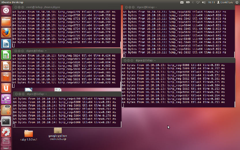
I’ve also tested this network under load using D-ITG with varying packet sizes and bursts. It performs superbly well. With some CoS config, it would be wise to put some safe guards in, but even using the smallest SRX devices, you can max out 100Mbps links without stressing the devices.
-
Kludge Avoidance: No weird cabling arrangements, No looping ports together on the same switch/line card, Avoid unreliable configuration. ↩︎